Supporting information |
Table 1. The acronyms of the wavebands.
|
Frequency
|
Acronym
|
| Region
|
Sub-region
|
|
|
Ultraviolet
|
|
UV
|
|
Visible
|
|
VIS
|
|
Infrared
|
Near Infrared
|
NIR
|
|
|
Short Wave Infrared
|
SWIR
|
|
|
Mid Wave Infrared
|
MWIR
|
|
|
Thermal Infrared
|
TIR
|
|
|
Far Infrared
|
FIR
|
|
Microwave
|
|
MW
|
Figure 1. Electromagnetic spectrum, atmospheric windows and wavelengths of maximum absorption in the atmosphere.
Table 2. Satellite missions provided high resolution imagery in a range of visible and infra-red bands.
|
Mission
|
Country
|
Date of launch
|
Date of termination
|
Altitude, km
|
Recurrent period, days
|
|
LANDSAT-1
|
USA
|
1972.07.23
|
1978.01.06
|
915
|
18
|
|
LANDSAT-2
|
USA
|
1975.01.22
|
1982.02.25
|
915
|
18
|
|
LANDSAT-3
|
USA
|
1978.03.05
|
1983.03.31
|
915
|
18
|
|
LANDSAT-4
|
USA
|
1982.07.16
|
2001.06.15
|
705
|
16
|
|
LANDSAT-5
|
USA
|
1984.03.01
|
Operating
|
705
|
16
|
|
LANDSAT-6
|
USA
|
1993.10.05
|
1993.10.05
|
-
|
16
|
|
LANDSAT-7
|
USA
|
1999.04.15
|
Operating
|
705
|
16
|
|
SPOT-1
|
France
|
1986.02.22
|
2002.02.04
|
822
|
26
|
|
SPOT-2
|
France
|
1990.01.22
|
Operating
|
822
|
26
|
|
SPOT-3
|
France
|
1993.09.26
|
1997.11.14
|
822
|
26
|
|
SPOT-4
|
France
|
1998.03.24
|
Operating
|
822
|
26
|
|
SPOT-5
|
France
|
2002.05.04
|
Operating
|
822
|
26
|
|
RESURS-O1 #1
|
USSR
|
|
|
|
|
|
RESURS-O1 #2 (KOSMOS-1939)
|
USSR
|
1988.04.20
|
1995
|
|
|
|
RESURS-O1 #3
|
Russia
|
1998.11.04
|
|
678
|
21
|
|
RESURS-O1 #4
|
Russia
|
1998.07.10
|
|
835
|
|
|
IRS-1A
|
India
|
1988.03.17
|
|
900
|
22
|
|
IRS-1B
|
India
|
1991.08.29
|
|
900
|
22
|
|
IRS-1C
|
India
|
1995.12.
|
|
817
|
24
|
|
IRS-1D
|
India
|
1997.09.
|
|
817
|
24
|
Table 3. Spaceborn sensors provided high resolution imagery in a range of visible and infra-red bands.
|
Instruments
|
Mission(s)
|
Type
|
Wavebands, mkm
|
Spatial Resolution, m
|
Swath width, km
|
TM
Thematic Mapper
|
Landsat-4,5
|
Imaging multi-spectral radiometer (VIS/IR)
|
VIS: B1: 0.45-0.52
B2: 0.52-0.60
B3: 0.63-0.69
NIR: 0.76-0.90
SWIR: 1.55-1.75
2.08-2.35
TIR: 10.4-12.5
|
VIS-SWIR: 30
TIR: 120
|
185
|
ETM+
Enhanced Thematic Mapper Plus
|
Landsat-7
|
Imaging multi-spectral radiometer (VIS/IR)
|
VIS: B1: 0.45-0.52
B2: 0.52-0.60
B3: 0.63-0.69
NIR: 0.76-0.90
SWIR: 1.55-1.75
2.08-2.35
TIR: 10.4-12.5
Panchromatic: 0.5-0.9
|
Panchromatic: 15
VIS-SWIR: 30
TIR: 60
|
185
|
HRV
High Resolution Visible
|
SPOT 1-3
|
High resolution optical imagers
|
VIS: B1 0.50-0.59
B2: 0.61-0.68
NIR: B3:0.79-0.89
Panchromatic: VIS 0.51-0.73
|
Panchromatic: 10
Multispectral: 20
|
60 (1 instrument)
117 (2 instruments).
steerable up to -27 deg off-track
|
HRVIR
High Resolution Visible and Infrared
|
SPOT-4
|
High resolution optical imagers
|
VIS: B1: 0.50-0.59
B2: 0.61-0.68
NIR: 0.79-0.89
SWIR: 1.58-1.75
Panchromatic: VIS B2 0.61-0.68
|
10m (0.64) or 20
|
60 (1 instrument)
117 (2 instruments).
steerable up to -27 deg off-track
|
|
HRG
|
SPOT-5
|
High resolution optical imagers
|
VIS: B1: 0.50-0.59
B2: 0.61-0.68
NIR: B3: 0.79-0.89
SWIR: 1.50-1.75
Panchromatic: VIS 0.49-0.69
|
Panchromatic: 5
Multispectral: 10
|
60 (1 instrument)
117 (2 instruments).
steerable up to -27 deg off-track
|
HRS
High Resolution Stereoscope
|
SPOT-5
|
High resolution optical imager
|
Panchromatic: VIS 0.49-0.69
|
Panchromatic: 10
|
120
|
HRS
High Resolution Stereoscope
|
SPOT-5
|
High resolution optical imager
|
Panchromatic: VIS 0.49-0.69
|
Panchromatic: 10
|
120
|
OPS
Optical Scanner
|
JERS-1
|
Imaging multi-spectral radiometer (VIS/SWIR)
|
VIS: B1: 0.52-0.60
B2: 0.63-0.69
NIR: 0.76-0.96
SWIR: 1.60-1.70
2.00-2.40
|
18x24
|
75
|
MSU-E
Multispectral high resolution electronic scanner
|
RESURS-O1 series
|
High resolution optical imagers
|
VIS: B1 0.5-0.6
B2 0.6-0.7
NIR 0.8-0.9
|
35x45
|
45-63 (pointable -30 deg from nadir)
|
|
LISS-I Linear Imaging Self Scanning
|
IRS-1A, IRS-1B
|
High resolution imager
|
VIS: B1 0.45-0.52
B2 0.52-0.59
B3 0.62-0.68
NIR 0.77-0.86
|
72.5
|
148
|
|
LISS-II Linear Imaging Self Scanning
|
IRS-1B
|
High resolution imager
|
VIS: B1 0.45-0.52
B2 0.52-0.59
B3 0.62-0.68
NIR 0.77-0.86
|
36.25
|
74
(either side of ground track with 3 km)
overlap: total 145
|
|
LISS-III Linear Imaging Self Scanning
|
IRS-1C, IRS-1D
|
High resolution imager
|
VIS: B1 0.52-0.59
B2 0.62-0.68
NIR 0.77-0.86
SWIR: 1.55-1.70
|
VIS-NIR: 23.5
SWIR: 70.5
|
141
|
|
PAN Panchromatic sensor
|
IRS-1C, IRS-1D
|
High resolution optical imager
|
VIS: 0.50-0.75
|
5.8-7.6
|
70.5
|
Table 4. Space missions with synthetic aperture radars (SAR).
|
Mission
|
Country
|
Date of launch
|
Date of termination
|
Altitude, km
|
Recurrent period, days
|
|
Seasat
|
USA
|
1978.06.28
|
1978.10.10
|
800
|
|
|
Kosmos-1870
|
USSR
|
1987.07.25
|
1989.07.30
|
250-280
|
|
|
Almaz-1
|
USSR
|
1991.03.31
|
1992.10.17
|
270-380
|
|
|
ERS-1
|
ESA
|
1991.07.17
|
2000.03.10
|
780
|
3, 35, 168
|
|
JERS-1
|
Japan
|
1992.02.11
|
1998.10.12
|
570
|
44
|
|
ERS-2
|
ESA
|
1995.04.21
|
Operating
|
780
|
35
|
|
RADARSAT-1
|
Canada
|
1995.11.04
|
Operating
|
798
|
3,7,24
|
|
Envisat-1
|
ESA
|
2002.03.01
|
Operating
|
800
|
35
|
|
ALOS
|
Japan
|
2006.01.24
|
Operating
|
691.65
|
46(SubCycle2)
|
Table 5. Shuttle Imaging Radar Missions.
|
Mission
|
Date of launch
|
Duration, days
|
Altitude, km
|
|
SIR-A
|
1981.11.12
|
2
|
|
|
SIR-B
|
1984.10.05
|
7
|
|
|
SIR-C/X-SAR
|
1994.04.09
|
11
|
225
|
|
SIR-C/X-SAR
|
1994.09.30
|
11
|
225
|
|
SRTM
|
2000.02.11
|
11
|
|
Table 6. Spaceborn synthetic aperture radars (SAR).
|
Instruments
|
Mission(s)
|
Wavebands
|
Incidence angle
|
Spatial Resolution, m
|
Swath width, km
|
|
SAR (Seasat) Syntetic Aperture Radar
|
Seasat
|
L-band 1.275 GHz,
HH polarization
|
20-26°
|
25x25 (4 looks)
|
100
|
|
EKOR
|
Kosmos 1870
|
S-band, 3.125 GHZ,
HH polarization
|
30-60°
|
25-30
|
25-30 steerable within 200 km,
left or right off-track
|
|
EKOR-A
|
ALMAZ-1
|
S-band, 3.125 GHZ,
HH polarization
|
variable 25-60°
|
<15
|
35-55 steerable within 350 km,
left or right off-track
|
SAR (RADARSAT)
Syntetic Aperture Radar C band
|
RADARSAT-1
|
C band: 5.3GHz,
HH polarization
|
|
Standard: 25 x28 (4 looks)
Wide beam (1/2):48-30 x 28m/ 32-25 x 28m (4 looks)
Fine resolution: 11-9 x 9m (1 look)
ScanSAR (N/W): 50 x 50m/ 100 x 100m (2-4/4-8 looks)
Extended (H/L): 22-19x28m/ 63-28 x 28m (4 looks)
|
Standard: 100
Wide: 150
Fine: 45
ScanSAR Narrow: 300 km
ScanSAR Wide: 500
Extended (H): 75
Extended (L): 170
|
AMI/SAR/Image
Active Microwave Instrumentation. Image Mode
|
ERS-1,2
|
C band: 5.3 GHz,
VV polarization
|
19.4-26.6°
|
<30 (3 looks)
|
100
|
|
SAR (JERS-1) Syntetic Aperture Radar
|
JERS-1
|
L-band: 1.3 GHz,
HH polarization
|
35°
|
18x18 (3 looks)
|
75
|
|
SIR-C/X-SAR
|
Space Shuttle STS-59, STS-68
|
C-band: 5.17 GHz,
L-band: 1.28 GHz,
X-band: 9.68 GHz,
polarizations
HH, VV, HV, VH
|
Look angle SIR-C: steerable up to ±23° from nominal 40°,
X-SAR: 15-60°
|
10-200, typically 30x30
|
C,L bands: 15-90,
X band: 15-40
|
ASAR
Advanced Synthetic-Aperture Radar
|
Envisat-1
|
C-band: 5.3 GHz,
with choice of 5 polarizations modes (VV, HH, VV/HH, HV/HH, or VH/VV)
|
|
Image, wave and alternating polarization modes: <30 (3 looks)
Wide swath mode: 150 x 150
Global monitoring mode: 950 x 950
|
Image and alternating polarization modes:
up to 100;
Wave mode: 5;
Wide Swath mode: 405;
Global monitoring modes: 400 or more
|
PALSAR
Phased Array Type L-band Synthetic Aperture Radar
|
ALOS
|
L-band: 1.27 GHz,
polarisations modes: VV or HH; HH+HV or VV+VH
|
Fine mode 8°-60°
ScanSAR 18°-43°
|
Fine mode 7-44m or 14-88m
ScanSAR 100m
|
Fine mode 40-70km
ScanSAR 250-350km
|
Figure 2. ERS-1, ERS-2.
Figure 3. RADARSAT SAR Operating Modes.
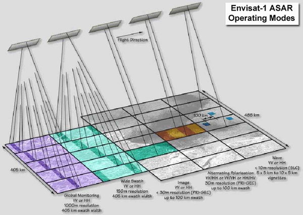
Figure 4. Envisat-1 ASAR Operating Modes.
Figure 5. ALOS PALSAR Operating Modes.
Table 7. Moderate Resolution Imaging Spectroradiometer (MODIS).
|
|

